LITIO.si
CAD out of the box™
Sheet metal add-ons for AutoCAD, GStarCAD, ZwCAD and BricsCAD

LITIO 2.0 Screen captures - Standard patterns


Do you need to create sheet metal ductwork patterns: rectangle to round transitions, cones, intersections, Ys, branches, bends, etc.?


LITIO 2.0 is an advanced sheet metal design program, that calculates the flat (unfolded) sheet metal [e.g.: metals like iron, stainless steel, brass, copper, aluminum, etc.] development of ducts [round, square, rectangle, polygonal, ellipse], transitions [including rectangle to round, ellipse to round, and much more, as well as free transitions], cones, pipe intersections, connections, Ys, triple Ys, elbows, taper elbows, fittings, etc.

Steps of use:


Installing and running LITIO 2.0...


Check LITIO2 installation instructions, or refer to the user manual.

Choosing your pattern type...


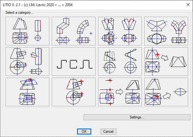
Select your sheet metal pattern category


Choose the type of your pattern:
  1. Transitions
  2. Bends and spheres
  3. Ys [and triple Ys] without a base piece
  4. Ys [and triple Ys] with a base piece
  5. Branches and intersecting 3D objects
  6. Standard and customized 2D profiles
  7. Helical augers and Helixes
  8. Existing 3D objects unfolder *
  9. Existing 3D objects plane trimmer *
  10. Standard and Customized main & leader [3D intersection trimmer]*.
  11. Standard and Customized transitions*.
  12. 2D curves and curve [polyline] extraction from existing 3D objects *


Note: Please be aware, that the items marked with * do not work with AutoCAD/GStarCAD/ZwCAD/BricsCAD 3D solids

Choosing a pattern...


Afterwards, chose the pattern you want. For example, you would like to make the development of a silo, a hopper, a pipe transition, a tube bend or fitting, a cylindrical duct, a square-to-round, a rectangle-to-round, etc.


Just pick a pattern from the dialogue or, if it is not in this particular page, browse up or down with the < MORE or MORE > buttons. You can even go back to the previous page to select again a different category, till you get familiar with the program.
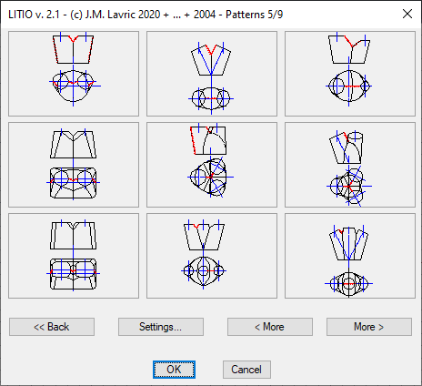


Choosing your sheet metal pattern


Parameter input...


Fill the dialog boxes with the values of the dimensions of your pattern.
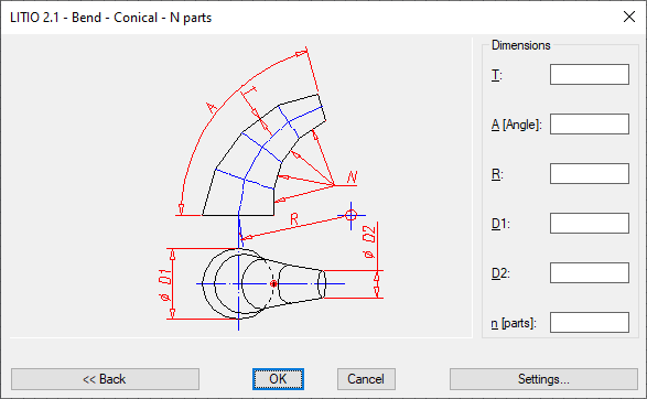

Input your sheet metal pattern parameters


3D Object, Development, and 2D Contour...


After finishing the input of parameters, the program draws the 3D object and the respective 2D unfolded development.
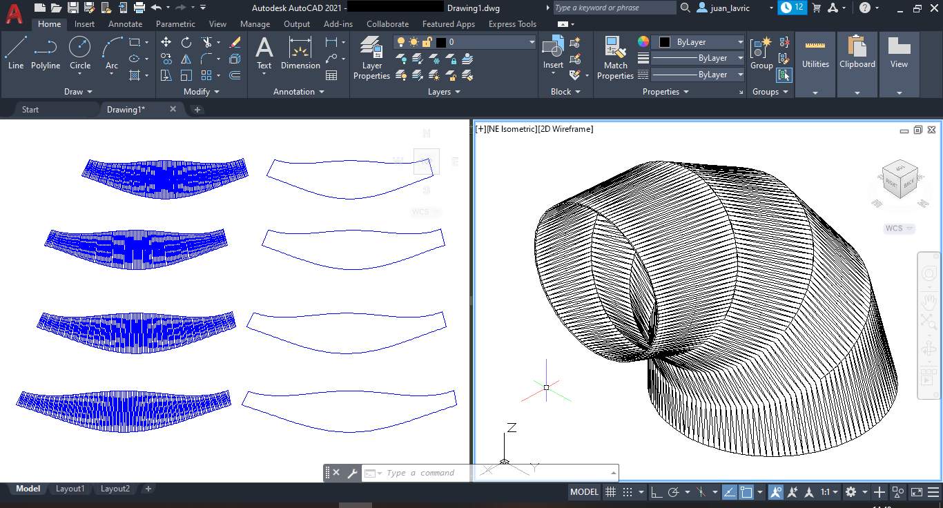


Get your sheet metal pattern 3D object, and 2D development and its contour


Afterwards, you can use the 2D developments for CAM cutting (plasma, laser, etc.) or manual cutting, by plotting them 1 to 1 (1 d.u. = 1 mm or 1 d.u. = 1 inch), and using them to mark sheet and cut.


Setting preferences...


At any of the dialogue boxes you can go to the Settings dialogue. There you can choose:
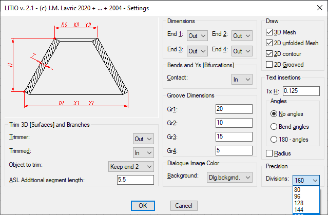

  • Dimensions: Inside, outside, or mid cross sectional dimensions, independently for ends 1, 2, 3 and/or 4.
  • Trimmer: Out/mid/in surface of the trimmer object as the trimmer surface. This is important for bevel preparation for welding.
  • Trimmed: Out/mid/in surface of the object to be trimmed (either of a dialogue or an existing 3D object picked) as the trimmed surface. Also important for bevel preparation for welding.
  • Object to trim: Keep end 1 or Keep end 2.
  • Contact: For bends and bifurcations, you can select if the parts have contact on the in/mid/out surface. This is important for bevel preparation for welding.
  • Groove measures: Seams can be welded or folded, depending on the sheet thickness. You can input, if they are relevant, dimensions for grove preparation allowance.
  • Dialogue Image Color: For better dialogue image visualization, you can change dialogue background color.
  • Draw: You can select to draw or not the original 3D surface, and the unfolded sheet, either as a mesh (to help you when bending the sheet), as 2D contour (to ease cutting), or as a 2D contour with grooved seems allowance.
  • Text insertions: New version 2.0 helps you bending or forming your patterns. You can have, on each generatrix of the 2D mesh representation, the bend angle, or the approximate bending radius on both ends.
  • Precision: You can also select the precision of the calculation of the developments.


Litio2 sheet metal for AutoCAD/GStarCAD settings


Metric Units/Imperial units: LITIO2 automatically sets the units according to the units used in the current drawing session (according to the values of MEASUREMENT and LUNITS system variables). (Refer to your AutoCAD/GStarCAD user manual for further information on Metric and Imperial units, and on the use of MEASUREMENT and LUNITS system variables).


Download you FREE TRIAL now!

First, choose your CAD platform

Then, Get your now! ...


... Or use the following secondary link.


If your browser does not support the download buttons, you can go to the downloads page.